Two-Switch Flyback Solution for LED Street Lighting
LEDs provide high efficiency and long life compared to conventional lighting sources. Therefore, they are becoming first priority of lamp types to reduce energy consumption for internal or external lighting. This is also the case in street lightings where better efficiency and longer life are essential for less cost. A switching power supply designed to power up LED lamp should also have high efficiency and robustness to assure maintenance free lifetime as long as LED lamp. Resonant converters are one of the most popular power supply topologies here since their performance delivers increased power efficiency. LLC resonant converter has drawn attention thanks to its features such as high power conversion efficiency and low voltage stress on secondary rectifier. However, complicated design and high manufacturing cost of LLC resonant converters have been obstacles to fast time-to-market and cost reduction. Another problem of LLC resonant converter is large circulating current that is required to maintain zero voltage switching (ZVS). It causes relatively high power consumption at light load. LLC resonant converter also has potential failure issue when MOSFET with poor body diode performance is used. Two-switch flyback converter is proposed as an alternative solution to overcome the limitations of the LLC resonant converter. With additional switch on the high side, leakage inductance energy is clamped and recycled back to input to improve efficiency. The dissipative snubber circuit is no longer needed. A 120W rated switching power supply is designed utilizing two-switch flyback topology. The details of design specification and test results are presented.
Two-switch quasi-resonant flyback topology
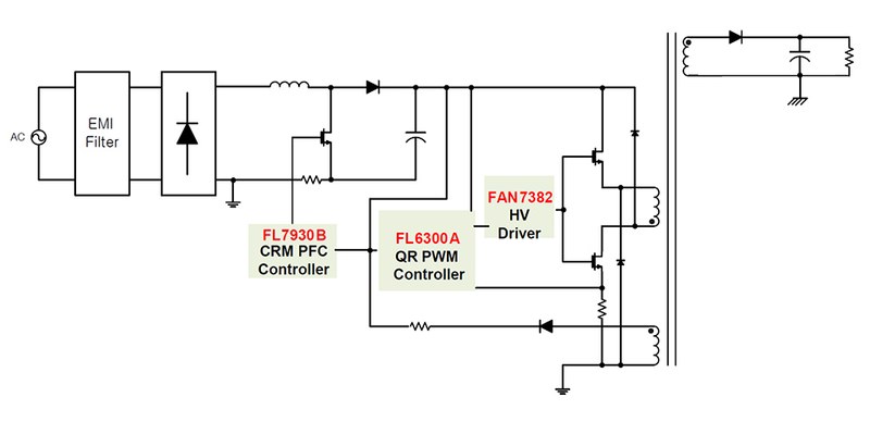
The two switching devices configuration virtually eliminates the loss in the clamping circuit. In addition, quasi-resonant switching feature of FL6300A effectively reduces the switching losses and enables high efficiency. Fig. 1 shows simplified schematic of the proposed two-switch quasi-resonant flyback converter. FL7930B is critical conduction mode PFC controller. FL6300A is quasi-resonant PWM controller. FAN7382 is high-side driver to drive two high and low side MOSFETs. The latest 600V, 385mOhm super-junction MOSFET in D-PAK is applied to both PFC switch and flyback switches. The conventional single switch flyback converter typically uses RCD clamping circuit that converts the energy of leakage inductance into heat dissipation. Two-switch flyback topology recycles the leakage inductance energy to the input side and the maximum voltage of MOSFET is clamped to the input voltage. Limiting the maximum voltage of MOSFET to the input voltage is a big benefit to reliability. In single switch flyback converter, the maximum peak voltage of MOSFET is very difficult to control. It is a function of leakage inductance and MOSFET current, and often exceeds the voltage rating of MOSFET resulting in breakdown of the MOSFET during fault conditions such as output short or overload. Clamping the maximum MOSFET voltage also allows large transformer turns ratio without increasing power dissipation in the clamping circuit and enables lower voltage stress in the secondary-side rectifier.
 Figure 1: Schematic of proposed converter
Design and evaluation
The target specification of two-switch quasi-resonant flyback converter for LED street lighting application is listed below. It should cover wide input voltage range and achieve high efficiency. The power rating is selected as 120W since it is typical requirement in LED street lighting. Another design target is removing bulky heatsink everywhere possible. All power devices are in surface mount type package such as D-PAK or D2-PAK.
|
Input Voltage Range |
90VAC~277VAC |
|
Input Voltage Frequency |
47Hz~63Hz |
|
Rated Output Power |
120W |
|
Rated Output Voltage |
49V |
|
Rated Output Current |
2.50A |
Table 1: Design specification
The minimum switching frequency is set to 45kHz. To have some margin, design is done for DC input voltage range from 300V to 430V. The maximum on duty for MOSFET is set to 0.45 for 300V input voltage considering drain-source falling time. This guarantees proper reset of the magnetizing current and MOSFET is turned on after drain-source voltage drops to input voltage.
Figure 2 shows efficiency measurement result according to input voltage and power MOSFET technology. Each MOSFET is the best Rds(on) device in D-PAK; 600mOhm with SuperFETÒ technology and 385mOhm with SupreMOSÒ technology. The SupreMOS MOSFET enables great improvement in system efficiency thanks to its smaller switching loss and less stored energy in output capacitance. The gain in efficiency with SupreMOS MOSFET is at least 2% over entire input voltage range.

Device operating temperature is measured using thermal imaging camera. Since surface mount devices without heatsink are used it is important to make sure operating temperature is within acceptable range. All power devices are well managed below 70degC at 90V input voltage condition as shown in Fig. 3.

Conclusion
Two-switch quasi-resonant flyback converter is proposed as LED street lighting solution and the performance is verified through typical design example fitted to target application. This topology is less sensitive to the transformer tolerance and gate drive timing, and allows robust and reliable power supply design as well. With all these benefits, two-switch quasi-resonant flyback converter could be an attractive alternative to sophisticated LLC resonant converter in LED lighting area.


